Avoidance/ Mitigation Of The Effects Of Common Forms Of Cracking In Cementitious Screeds

SCREED MIX DESIGNS

Aggregate is usually 0–4 mm and is mixed with cement in the ratio of 1:3 or 1:4 cement to sand, depending on strength requirements and drying requirements. For total screed thicknesses in excess of 50 mm, the use of 0–8 mm aggregate should be considered, or a fine concrete screed, since these screeds are less prone to shrinkage cracking and have improved drying characteristics’. The 0-8 mm aggregate can offer quite significant improvements. Polymer modified screeds can exhibit much lower shrinkage than unmodified screeds; shrinkage of Ronafix Pre-packed Screed 6-50mm is 0.01%, similar to an epoxy resin mortar.


CURING OF SCREEDS

Adequate curing of cementitious screeds will reduce the effects of drying shrinkage on flooring applied at a later stage and should eliminate plastic shrinkage cracking (see the next section).


Attention to good curing practice may also reduce the risk of curling in unbonded and floating screeds, by reducing differences in cure rate throughout the screed thickness; strong sunlight must be prevented from shining on a screed surface, commissioning of underfloor heating must not commence and radiant heat must not be introduced until the tensile strength of a screed is sufficient to resist shrinkage and until sufficient residual moisture has evaporated.

PLASTIC SHRINKAGE CRACKING

Plastic shrinkage cracking is a result of failure to adequately cure a screed either by delaying protection of the screed surface against the drying effects of direct sunlight and/ or drying winds, or taking no action at all. Exposure of screeds and concrete to direct sunlight and/ or drying winds causes moisture loss from the surface, producing a “crust”. Curing stress below the crust causes tear like cracks to appear in the weak surface layer. The following image is an illustration of classic plastic shrinkage cracks. Some plastic shrinkage cracking can take the form of fine, hair-line cracking in the surface of the screed and often only affecting any laitance drawn to the surface during trowelling of the screed. This is unlikely to present any issues with rigid flooring and tile adhesives can be selected which will provide some form of stress relief to accommodate any slight movement.


Some screed products gain strength too quickly for effective use of curing media and these products should only be applied when there is light ventilation and the screed is not exposed to direct sunlight. Screeds which do

not gain strength as quickly should be cured with spray applied curing membrane, or with tight fitting polythene. When polythene is used, care must be taken to fully seal the edges to prevent air movement under the polythene. Curing with polythene must be delayed until the surface of the screed is tack free and in adverse conditions, the condition of the screed surface may be too advanced to prevent plastic cracking before polythene is laid. Ronacrete Curing Membrane, or similar water based curing agent, is preferred for exterior use because it can be sprayed using back-pack spray equipment (preferably Gloria 410 T or 510 T) as soon as the screed has been finished, reducing the risk of plastic cracking caused by drying winds and/ or strong sunlight. Water based curing agents are 50% efficient and may not offer the same protection as 90% efficient membranes but this must be weighed against the delay required before application of 90% efficient membranes. Note that Ronacrete Curing Membrane will increase the drying time of screeds and when early drying is required, Ronacrete Curing Membrane should be removed after a minimum of approximately 24-36 hours 200C when curing rapid drying screeds/ polymer modified screeds and up to 7 days when curing standard screeds.

STRESS RELIEF/ RESTRAINT CRACKING

Screeds laid in long narrow bays are likely to form their own joints, in the shape of stress relief cracks, typically spanning the full width of a bay. Concrete slabs laid in aircraft hangars by the Royal Engineers during World War II were laid in square “hit and miss” bays of limited dimensions, to ensure that curing stress was as low and as even as possible and that when missed bays were laid, initial cure in adjacent bays had already taken place. The risk of stress relief cracking is low when screed bay proportions do not exceed 3:2 length: width ratio but the risk increases with the disparity in proportions and corridors/ footpaths are at high risk of lateral stress relief cracking. Bay joints may be formed by laying hit and miss, by cutting of joints or a combination of the two methods. Joints cut across the width of bays laid in strips

may be executed during laying of screeds, using the edge of a steel float to cut to a depth of ≥ 50% of screed thickness. Cuts may then be trowelled over to eliminate lipping. Early age saw cutting is more popular and more practical when screeds are not laid in strips but it carries a risk of crack formation when saw cutting is delayed, particularly in screeds where the onset of high levels of curing stress occurs much earlier than expected by the contractor. Fine stress relief cracks are unlikely to present a problem in areas to be carpeted or overlaid with resilient flooring such as vinyl sheet or linoleum, but may cause cracking of tiles and other rigid floorings. The use of an uncoupling membrane applied to the screed, such as Schlüter®-DITRA 25 is advisable in areas where rigid flooring such as tiles or stone flooring are to be laid, to separate rigid flooring from cracked screed. Where tiles are to be applied directly to screeds, care must be taken to ensure that correct screed bay proportioning is strictly adhered to and that bay joints, stress relief joints and movement joints in screeds coincide with grout joints and movement joints in tiles.

There are a number of positions where stress related cracks may occur, other than in overlong bays, principally at re-entrant corners and other positions where the screed may be restrained during curing. There is little to be done to prevent hairline cracking at the sites of restraints, other than correct positioning of isolation joints (which may reduce the risk of cracking) at screed perimeters, including columns, manholes etc., and positioning of steel reinforcement fabric, which will limit the width of cracks after they have formed and where rigid flooring is to be laid, use of an uncoupling membrane should be considered.

Screed crack at re-entrant corner mirrored in tiles

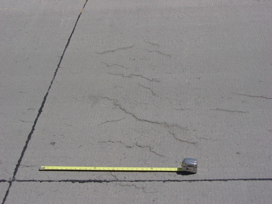
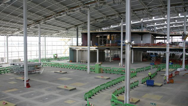
DRYING SHRINKAGE CRACKING

Attention to adequate provision of bay joints in the screed should considerably reduce the occurrence of drying shrinkage cracks and as far as possible joints in bonded screeds should coincide with joints in the slab, to avoid screed cracking caused by opening of joints in concrete base. See the FeRFA Guide to Specification and Application of Screeds (2.7.1 below) for further information.


FERFA GUIDANCE NOTE No. 15

The following is an extract from the recently issued FeRFA Guide to Specification and Application of Screeds, co-authored by Dr Malcolm Bailey of Radlett Consultants and Ronacrete Limited, with relevant passages highlighted. Copies of the guide are available on request from technical@ronacrete.co.uk or may be downloaded from the FeRFA website http://www.ferfa.org.uk/pdf/FeRFAPublications/TGN15GuidetoScreedsAugust2017-RIBAApproved.pdf


2.7.1 Bay sizes
Bonded and unbonded levelling screeds are normally laid in strips some 3 m to 4 m in width. This is to facilitate the use of screeding bars down either side which are used to ensure the correct thickness of screed/surface level. Alternate bays are laid, the bars removed and the infill strip thickness/ surface level is then based on the finished strips either side. Stress relief joints are usually formed every 5 m – 6 m down each strip. Such joints are either formed by cutting through with a trowel or saw-cutting the hardened screed. When choosing to saw cut a screed, the contractor should consider how soon after laying the screed should be cut; stress relief cracks may be formed in fast drying or high strength screeds at a very early stage in the curing process.


The setting out of such bays will depend on several factors. In a bonded screed the joints should follow closely the joints in the concrete base since it is inevitable that these will open and cause a crack in the screed. Similarly, sealant filled expansion/movement joints in the structure should never be screeded over.

In a floating screed designed to receive rigid floorings, bay sizes are normally limited to 40 sq m and positioning of joints will depend on the layout of the heating pipework system if underfloor heating is the reason for using a floating screed.


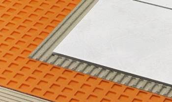
If ceramic tiling is to be laid as the final floor finish, bay joints in the screed may also need to be carefully set out to coincide with the bay joints in the tiling system.


Long thin strips such as corridors are prone to cracking and should be provided with stress relief joints at intervals, particularly as the screed tends to become restrained at doorways and junctions.


Cementitious (e.g. granolithic) and polymer modified wearing surfaces should be considered in the same way as bonded levelling screeds and joints should coincide with those in the underlying concrete slab.
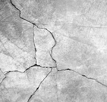
 

2.7.2 Cracking
Cracking is caused by either the external forces applied to the screed exceeding the relatively weak tensile strength of the screed or the internal forces within the screed exceeding its tensile strength.


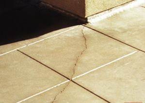
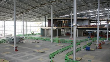
External forces can be applied by the building itself or its major structural components. Hence general movement of the building, e.g. flexing of suspended floors, foundation settlement, thermal expansion and contraction, can exert significant tensile forces on the screed which it does not have the tensile strength to resist. The most common external force is between adjacent ground-supported concrete slabs which are shrinking away from each other in the long drying out period. A screed which is bonded to both slabs and is continuous over the joint between them will inevitably crack.


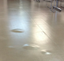
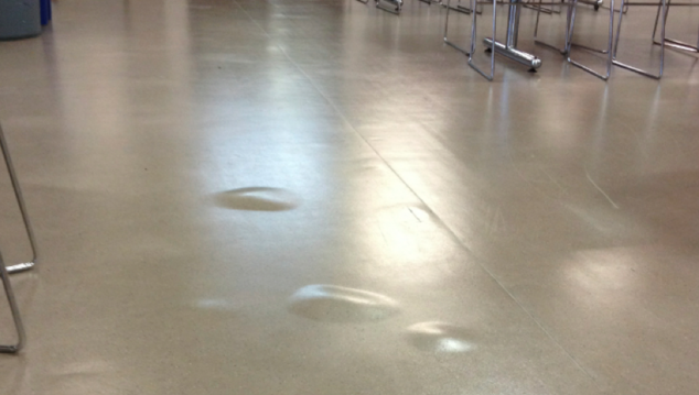
Internal forces are caused due to the screed itself trying to shrink due to loss of its moisture content. In theory as a floating or unbonded screed dries and shrinks, the edges of the screed will move evenly inwards towards the centre of the area. Unfortunately in practice this may not happen either because the drying and thus the shrinkage is uneven throughout the area of screed, or because the screed becomes restrained at one or more places.


Restraint of the screed, thus preventing it shrinking evenly can be caused by a number of factors. Internal columns in the building, re-entrant corners, manholes, service ducts typically can cause restraint. However, the most common cause is the weight of the screed itself and the friction that is generated thereby on whatever is supporting it. This is why it is important that the concrete slab surface in an unbonded screed is as smooth as possible. It should be clearly understood that reinforcement in the screed will not prevent cracking. It only limits the crack width. The crack will be initiated long before the reinforcement can have any effect.

RonaScreed FastDry Prompt – benefits and drying

RonaScreed FastDry Prompt (formerly RonaScreed 8 Day Overlay) is so-called because it is a fast-drying screed additive which enables a 50mm thickness of 3:1 sand/ cement screed to be overlaid with moi ...

Read more

Drying of Screeds

BS 8204-1 “Concrete bases and cementitious levelling screeds to receive floorings — Code of practice” section 6.11.1 suggests the following calculation for drying of screeds with no fast drying additi ...

Read more

Avoidance/ Mitigation Of The Effects Of Common Forms Of Cracking In Cementitious Screeds

Aggregate is usually 0–4 mm and is mixed with cement in the ratio of 1:3 or 1:4 cement to sand, depending on strength requirements and drying requirements. For total screed thicknesses in excess of 50 ...

Read more

Here to help...